CurrentSky · AI CAD Engine
AI-Powered Geometric Synthesis
From a rough sketch to a printable, mechanical part.
Demo
Watch it forge a part
Bridging the gap between imagination and physical reality — one forged part at a time.
What is Forge3D
An AI forge for real parts
Forge3D is an AI-powered CAD workspace that turns engineering concepts and hand-drawn sketches into professional, additive-ready 3D models. Born from the need to speed up prototyping for complex projects, it now serves as a universal forge for high-precision components.
The vision: democratize manual design by replacing steep learning curves with intuitive AI guidance. Whether you’re building functional parts for aerial systems or custom mechanical spares, Forge3D handles the geometric synthesis — moving toward a future where engineering intent is the only tool you need.
The engine
Main objectives
Rapid functional prototyping
Go from concept to a printable, functional part in a fraction of the usual time.
Precision geometric synthesis
Exact, manifold geometry — components that hold real mechanical tolerances.
Sketch-to-3D input
Multimodal analysis turns hand-drawn sketches and prompts directly into models.
Automated CAD code
Generates executable geometric code (JSCAD, FreeCAD) — not a fragile mesh.
Zero-knowledge workflows
No CAD expertise required — describe the intent, and the engine handles the rest.
Under the hood
Advanced synthesis & logic
Forge3D leverages a multi-layered AI architecture driven by the latest coding models, including GPT-5 Codex — enabling semantic understanding of mechanical constraints and real-time validation of geometric logic.
Future iterations will integrate structural simulation and material analysis, bringing generative engineering directly into the hands of makers and hardware startups.
Why Forge3D
Deterministic by design
While standard AI tools produce chaotic meshes, Forge3D outputs executable geometric code (JSCAD and FreeCAD). Every part isn’t just a visual representation — it’s an actual mechanical component: manifold, scalable, and ready for the 3D printer.
Case study
From text to 3D model
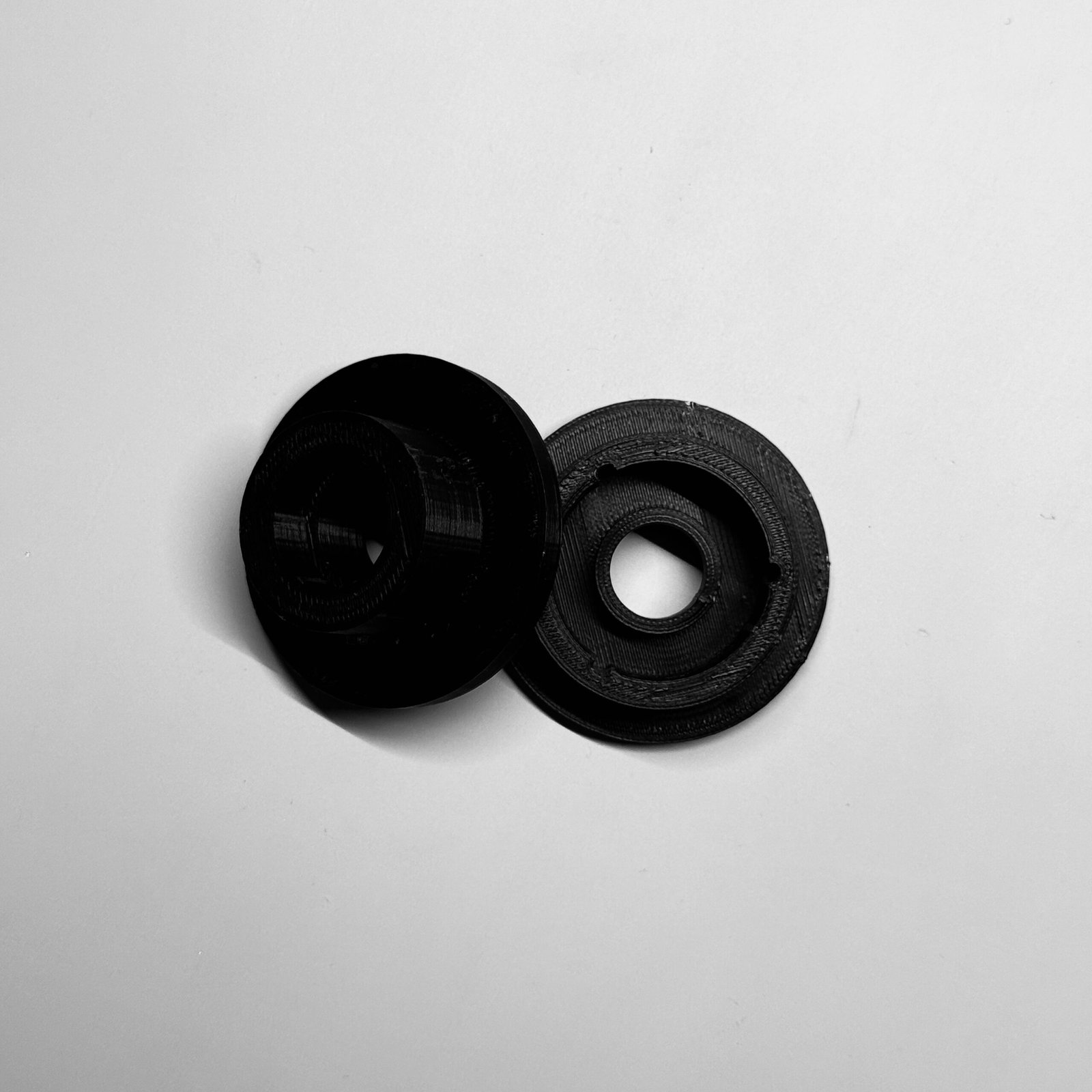
Photo: a functional component designed 100% by Forge3D and printed in PLA.
The synthesis process
- 01. Conceptual inputThe objective: design a “Quick-Release Dock Connector for a Modular Robot” — a robust mechanical interface, with no pre-existing blueprints and no manual CAD modeling.
- 02. AI-driven logic synthesisUsing the GPT-5 Codex engine, Forge3D calculated precise tolerances for a reliable connection, engineered alignment rails for stable engagement, and optimized the load-bearing surfaces for repeated docking cycles — outputting executable JSCAD code.
- 03. Geometric verificationThe synthesized model was inspected in our Three.js engine: a visual audit of proportions, and a check that the generated geometry was manifold and error-free for a clean STL conversion.
- 04. Final fabricationThe part was sent to a 3D printer. Total time from thought to physical component: less than 15 minutes (excluding print time), saving roughly 4 hours of manual professional modeling.
How it works
From sketch to 3D
Forge3D transforms hand-drawn or technical sketches into precise 3D models through a robust four-stage pipeline.

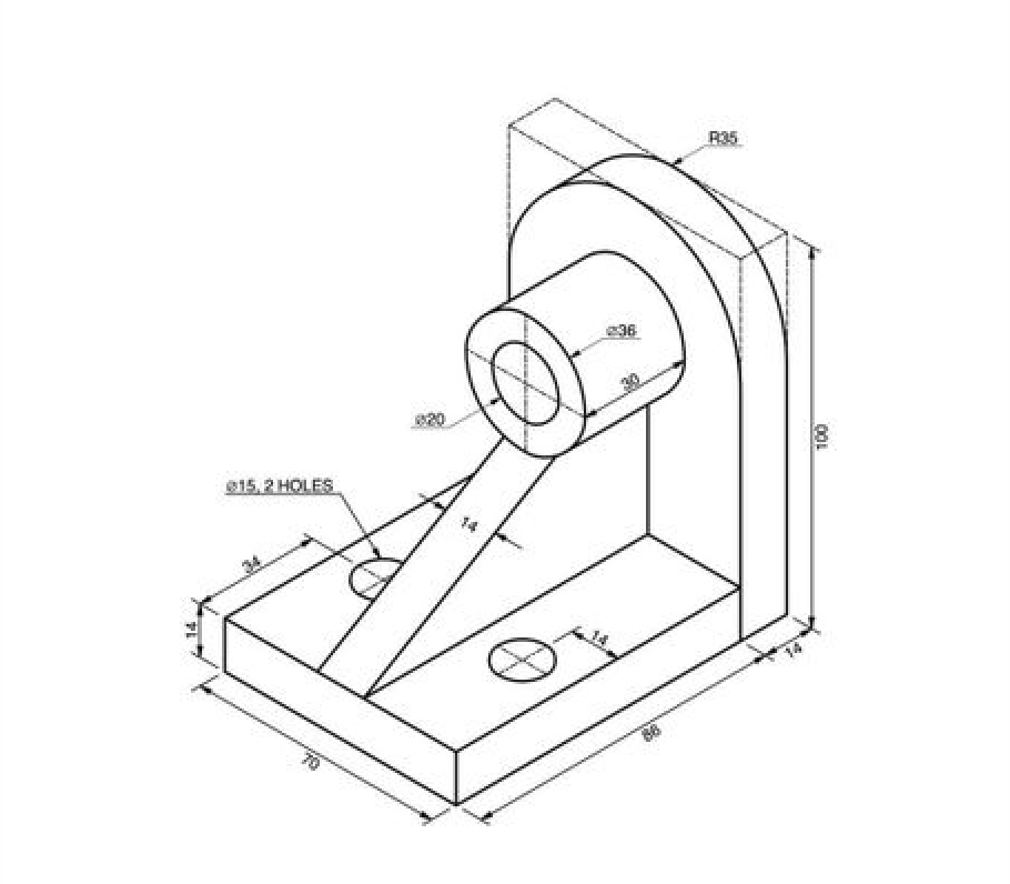
Photo: the initial hand-drawn sketch with dimensions and proportions.
1. Sketch input
The process begins by uploading a sketch of the desired object — hand-drawn or digital — that includes all necessary dimensions, proportions, and annotations required to define the geometry.
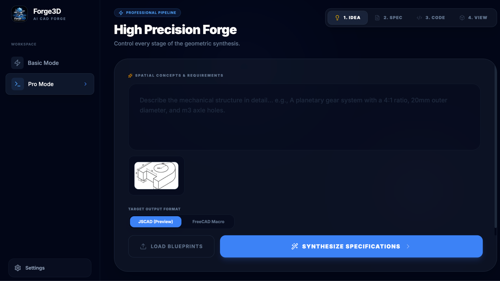
Photo: the AI analyzes the image and outputs a highly detailed textual specification.
2. Intelligent text interpretation
The system analyzes the sketch and converts it into a detailed textual specification. This description captures the full structure of the object — geometry, dimensions, relationships between components, and assembly logic.
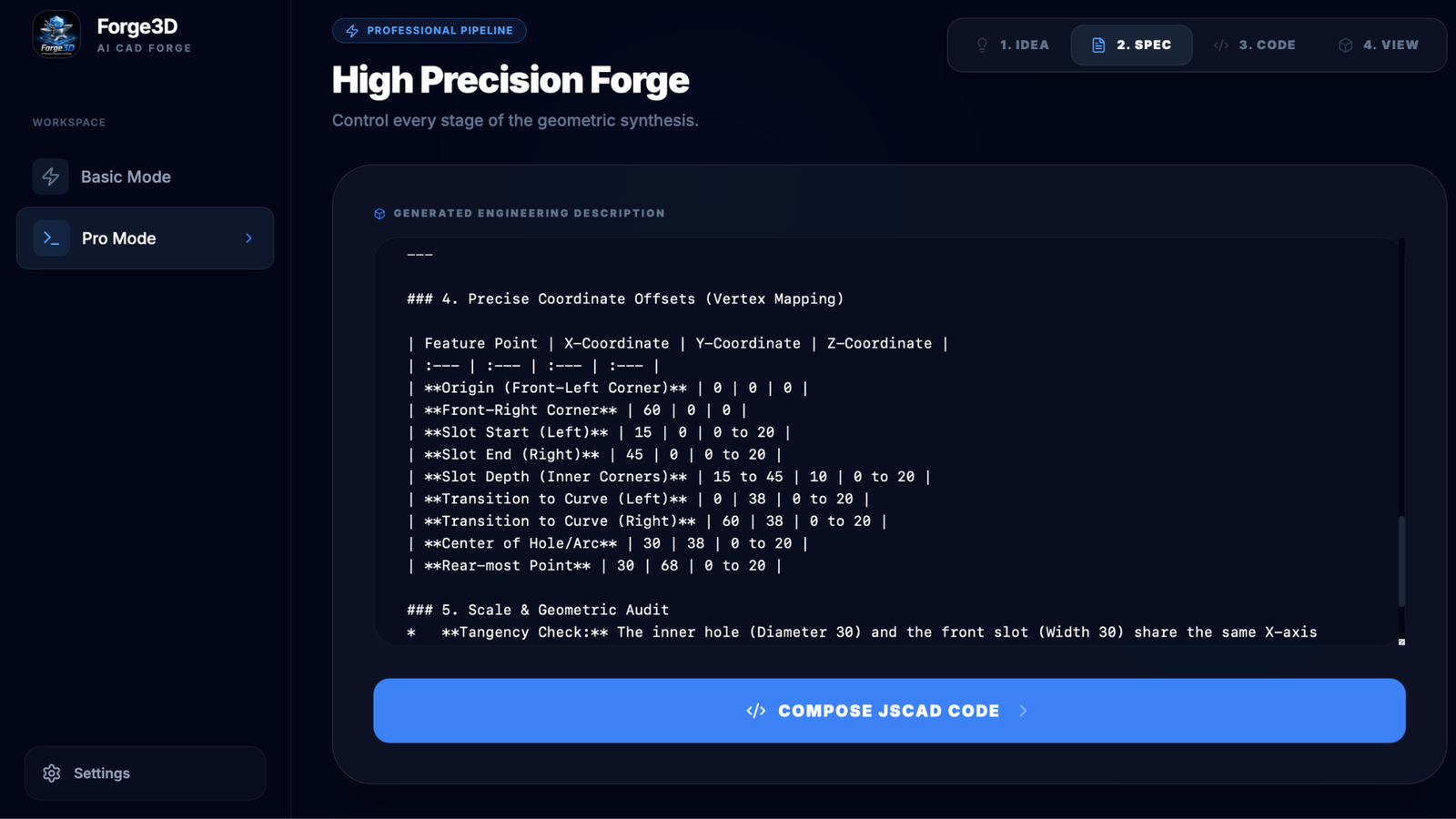
Photo: generated detailed textual specification.
3. Code generation & automated audit
Based on the generated specification, the application produces CAD code to construct the 3D model. An additional AI auditing layer then reviews and refines this code, detecting and correcting potential errors to ensure accuracy and structural integrity.
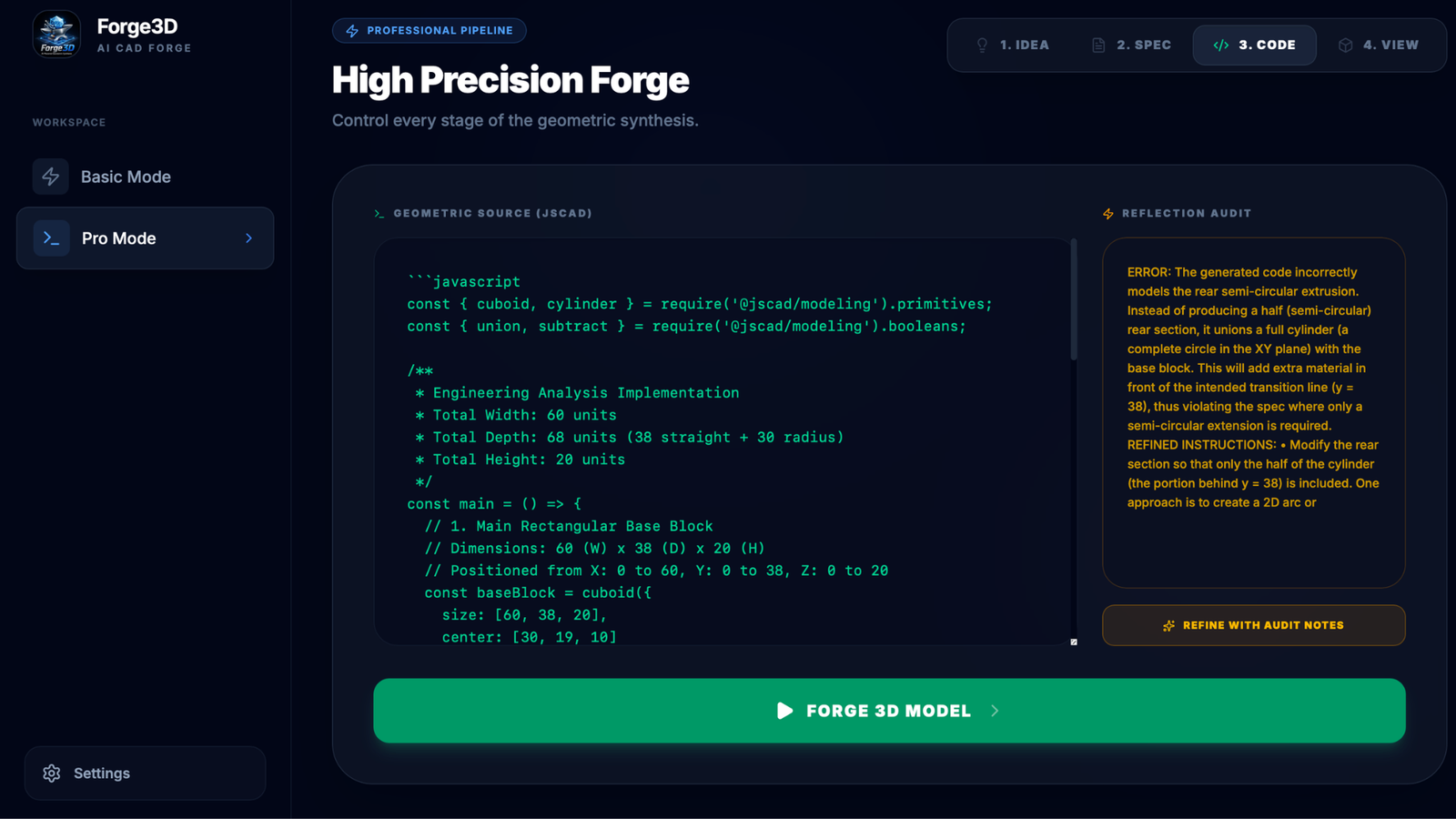
Photo: generated CAD code being audited and corrected by the secondary AI layer.
4. Model visualization & export
Finally, the generated model is rendered within the application for validation. Users can inspect the result, verify correctness, and export the finalized 3D model as an STL file ready for manufacturing or further use.
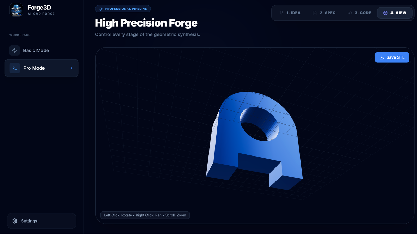
Photo: the final 3D model rendered and ready for STL export.
More examples
Other examples
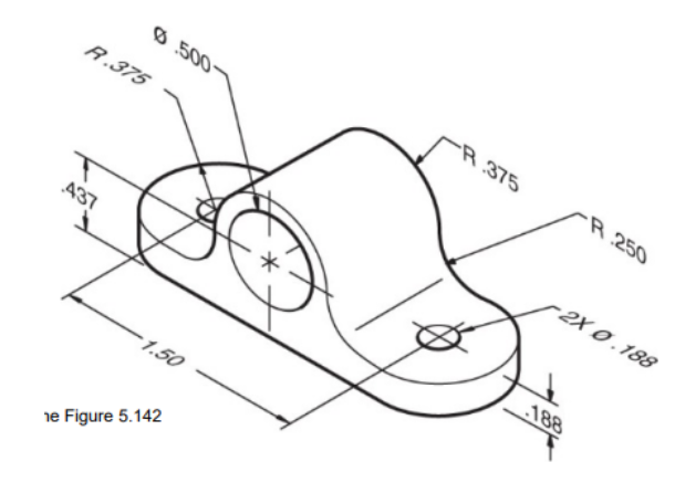
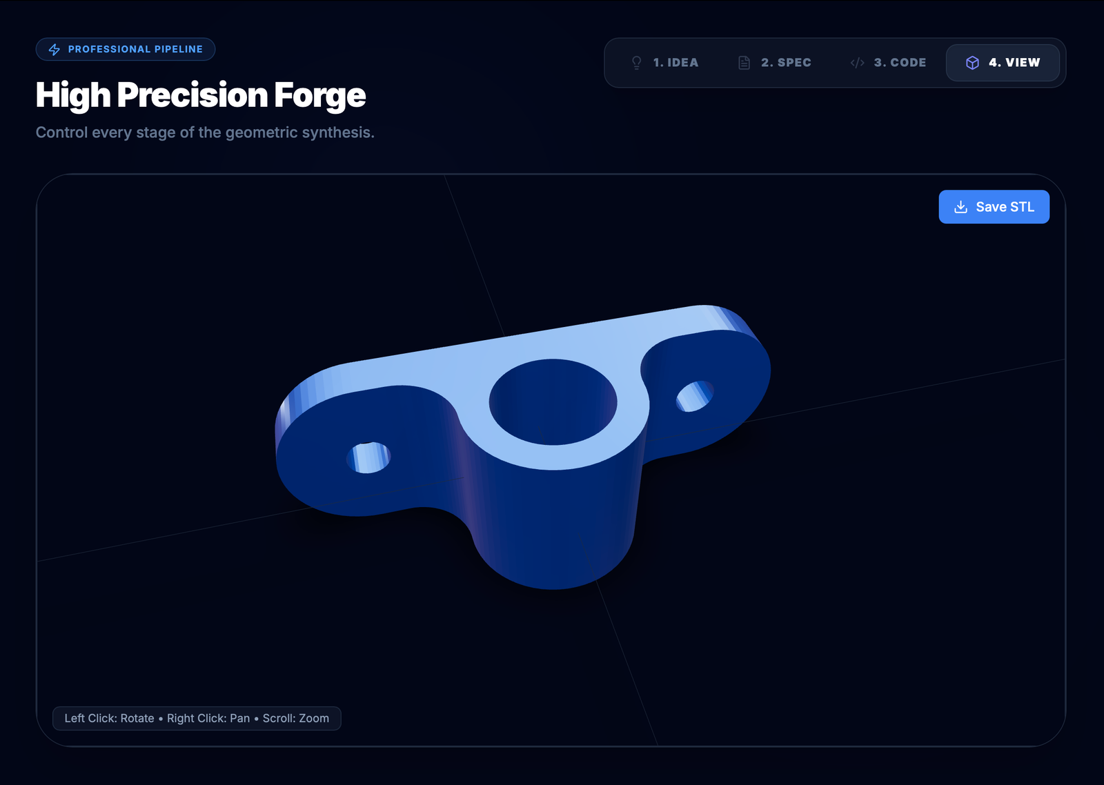
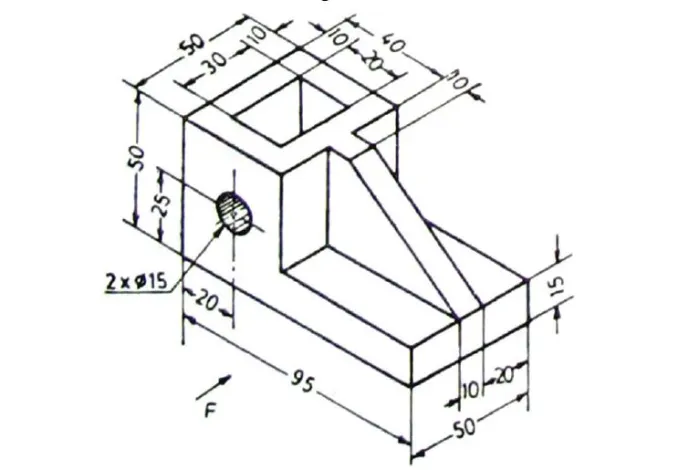
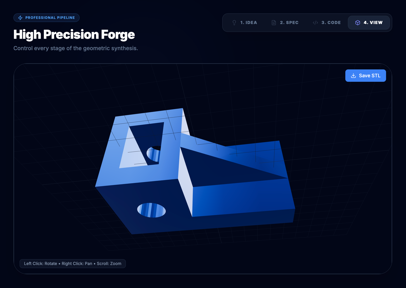
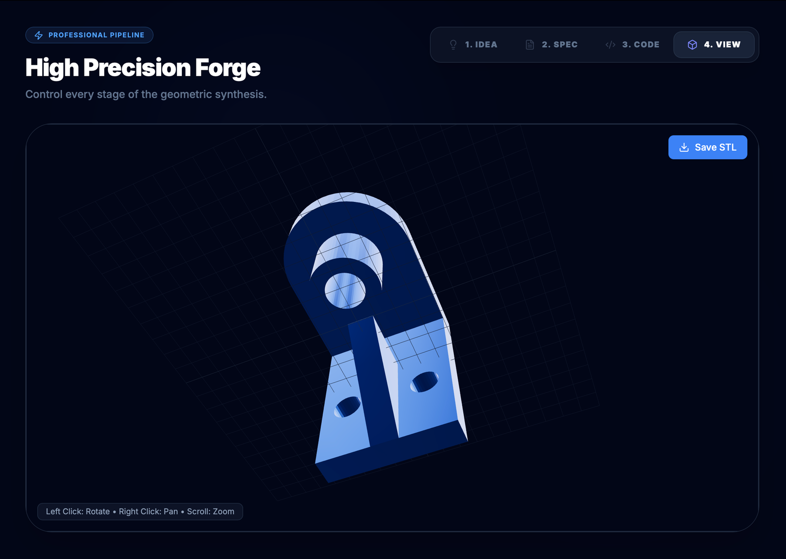
Each pair: the input drawing on the left, and the 3D model Forge3D generated from it on the right.
Studio mode
Design assemblies, not just parts
An interactive workspace for designing complex, multi-part 3D assemblies.
- Multimodal sketch-to-3D — draw freehand lines on a 2D canvas, from scratch or as annotations over the 3D model, and the AI converts the drawing into geometry.
- 3D marker tool — drop coordinate pins directly on part surfaces to indicate exactly where edits, holes or additions should happen.
- Parts & assembly panel — a tree view to manage, rename, hide/show, group or delete independent CAD parts.
- Workspace project import — bring parts and sub-assemblies across different design projects.
- Real-time viewport gizmos — select parts and use manual Move, Rotate and Scale handles; adjustments compile straight back into the JSCAD code.
The loop
Describe. Mark. Refine.
01
Describe the part
Type what you want in plain language and Forge3D builds the geometry — with a bounding box, live dimensions and a version history you can step back through.
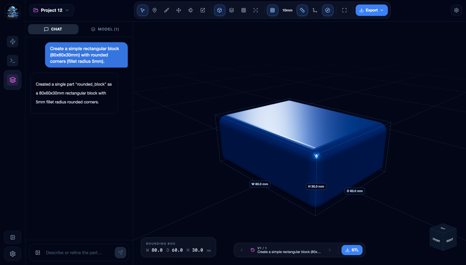
Prompt in, part out — the block is generated with its bounding box and live dimensions.
02
Mark the spot
Switch to the marker tool and click the model. A numbered pin records the exact coordinates of the point you want to change.
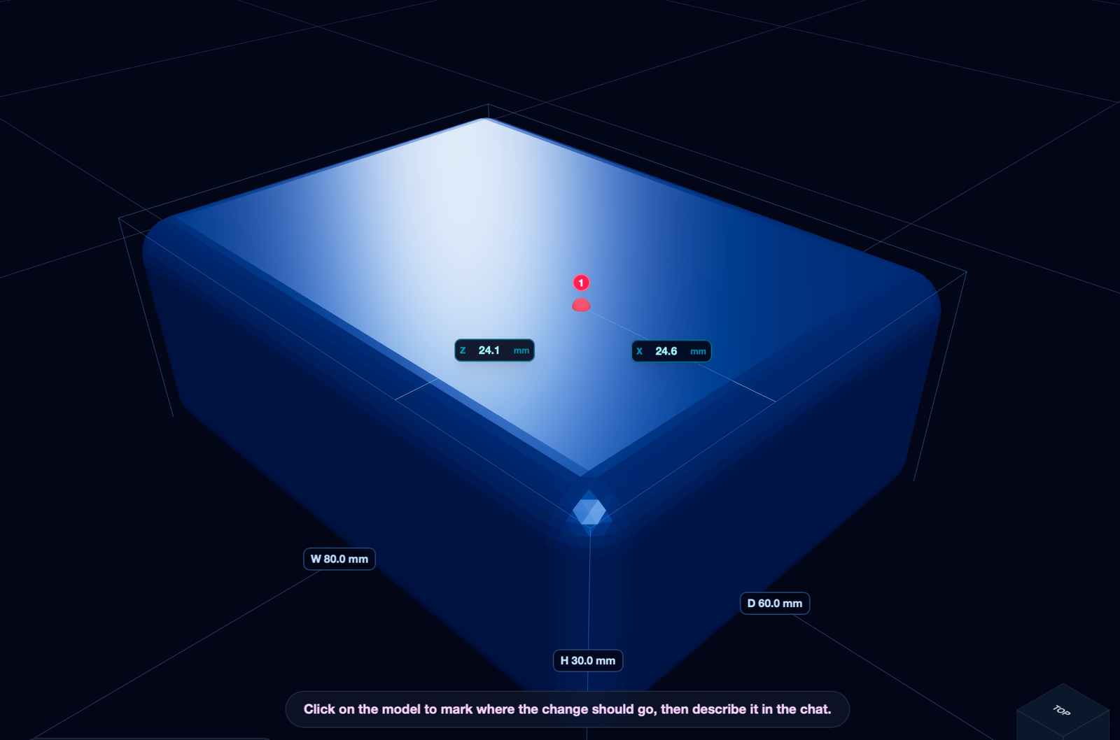
Click the surface to drop a coordinate pin exactly where the change should happen.
03
Refine in words
Back in the chat, describe the edit at that mark. The AI recompiles the JSCAD and applies the change in place — here, a deep circular pocket.
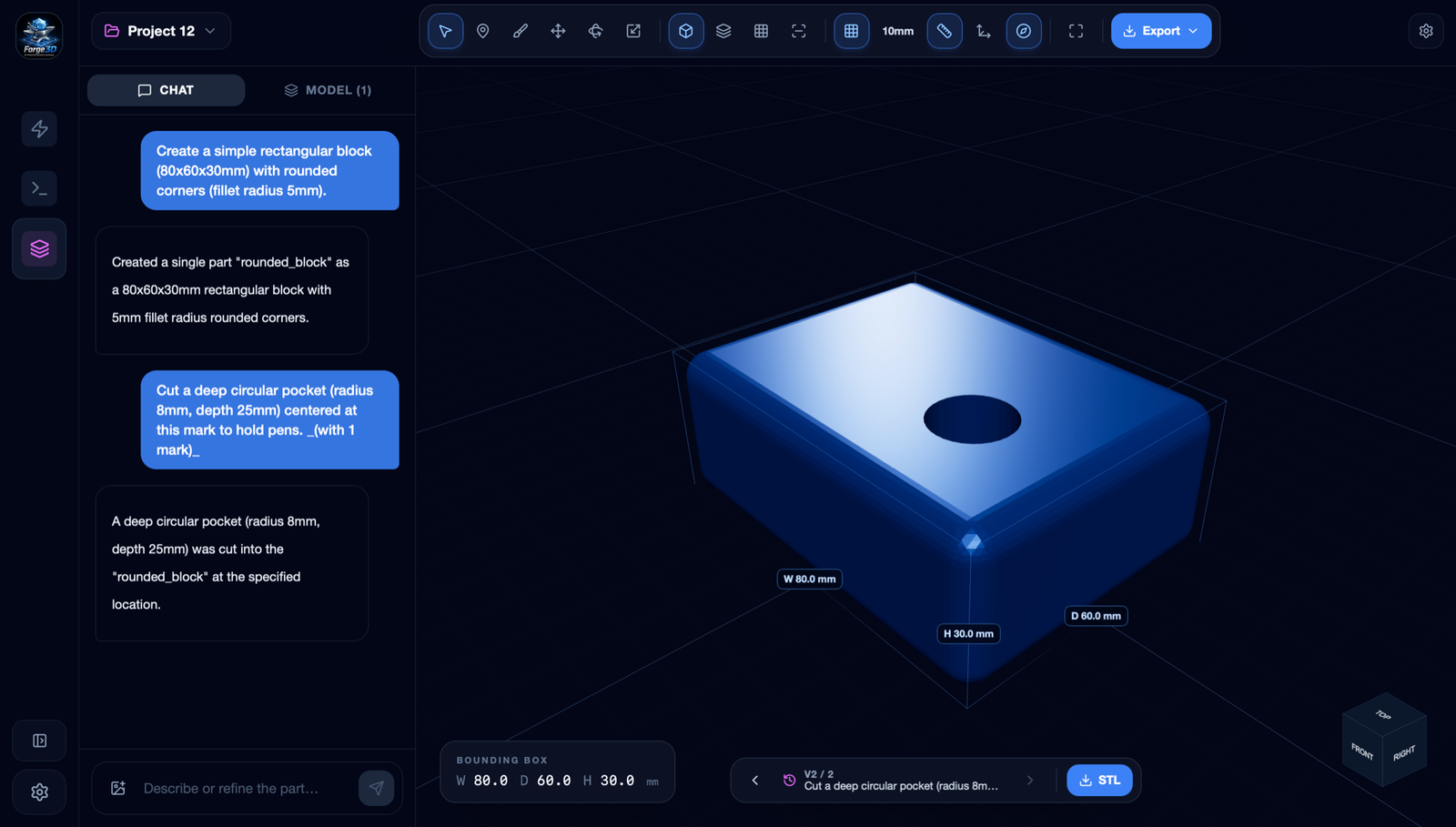
Describe the edit at that mark — “a Ø8 mm pocket, 25 mm deep” — and it’s cut into the part.
Deterministic CAD Synthesis ✦ Multi-Format Export ✦ Real-Time 3D Rendering ✦ GPT-5 Codex Logic ✦ Additive-Ready Geometry
Deterministic CAD Synthesis ✦ Multi-Format Export ✦ Real-Time 3D Rendering ✦ GPT-5 Codex Logic ✦ Additive-Ready Geometry
Deterministic CAD Synthesis ✦ Multi-Format Export ✦ Real-Time 3D Rendering ✦ GPT-5 Codex Logic ✦ Additive-Ready Geometry
Describe intent. Forge the part.
Building functional hardware and want the geometry handled for you? Let’s talk.